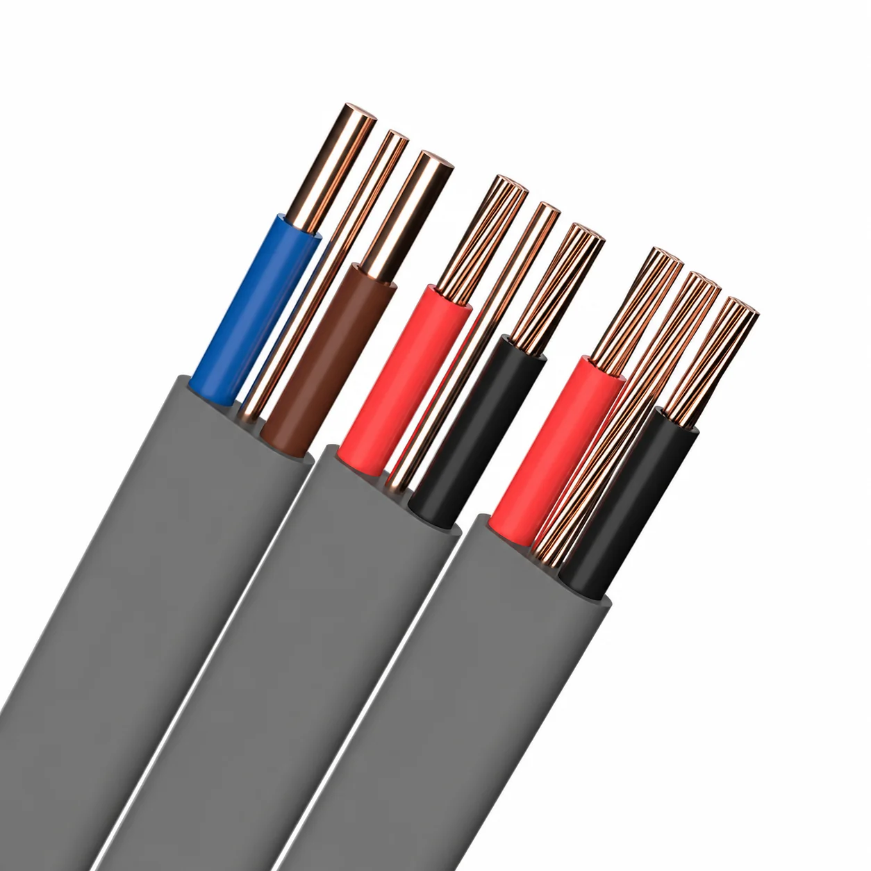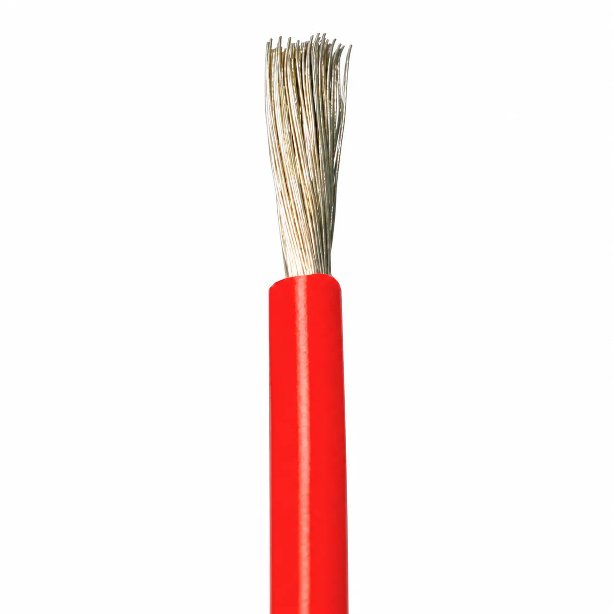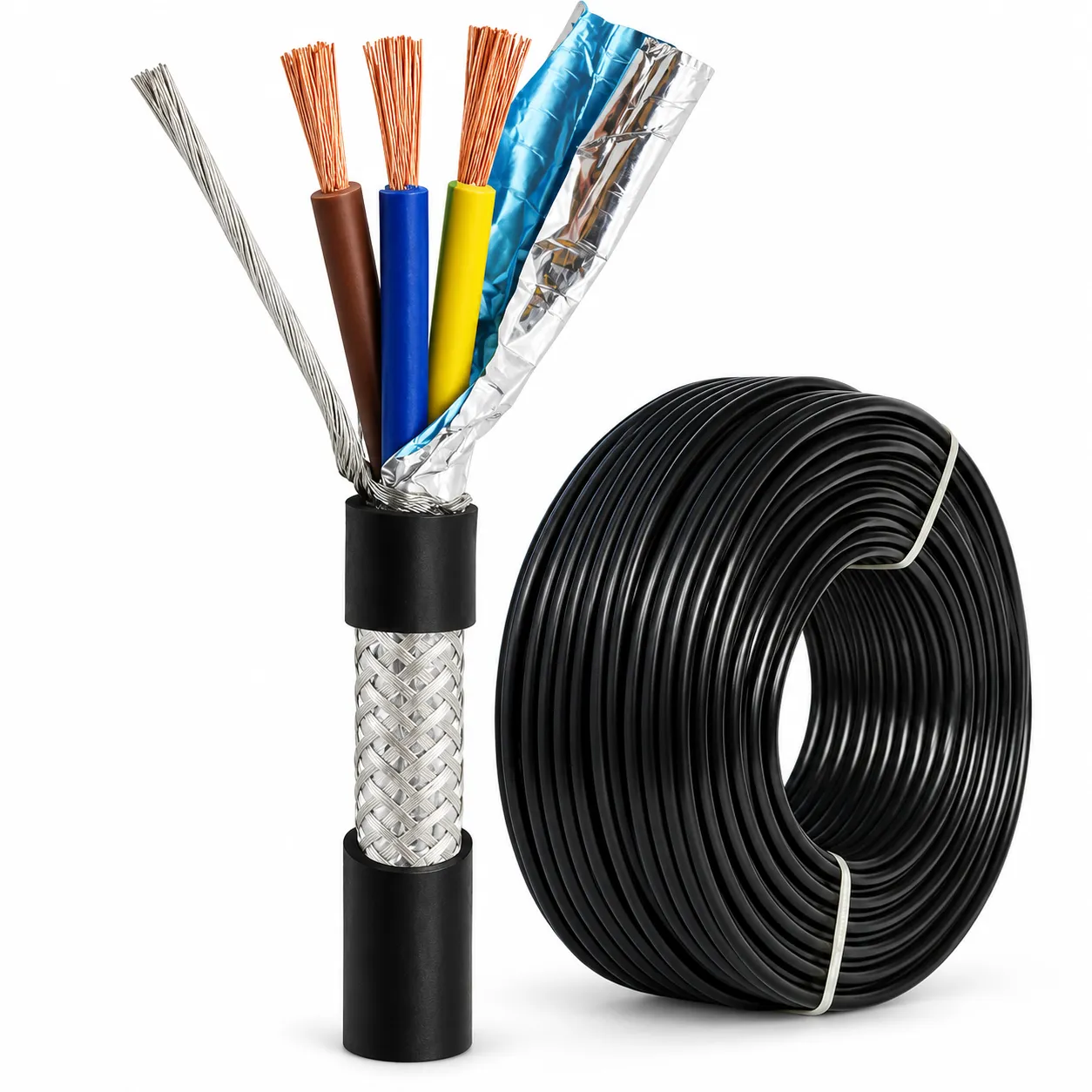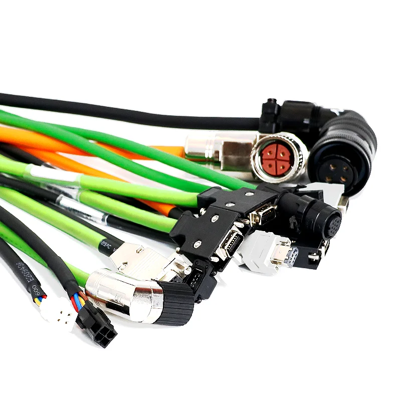
Series illustrations. Actual configuration is subject to the confirmed drawing.

Industrial Control Servo Encoder Sensor Adapter Cable 4/6/8/10/12-Core 0.14/0.25/0.34/0.5mm² AL/Braid Shield

Share
  • Quotation & delivery: Include your required quantity, destination and timing in the enquiry. Confirm the selected build, lead time, shipping charges and any return terms in the agreed quotation before ordering.

Product description
Quotation & delivery
  • Core count
    Multiple core options
    Nominal size
    Multiple mm² options
  • Rated voltage
    Multiple voltage options
  • Conductor Material
    Tinned Copper ( as request )
    Connector Type
    Adapter
  • Insulation Material
    PTFE, Silica Gel, Rubber, PVC, PBT, PET, Nylon, High insulation polyolefin / PVC / XLPE (customizable)
    Length
    1m, 1.5 m, 300 mm, 500 mm, 450 mm, 400 mm, 350 mm, 250 mm, 200 mm, 150 mm, 120 mm, 100 mm, 15 cm, 10 cm
  • Rated Voltage
    600V, 12V, 380 V, 110 V, 240 V, 220 V
  • Application
    Power, PCB, Electronic, Computer, Machines, Automobile, Home Appliance, Motorcycle
    Jacket Material
    Aluminum, Copper, PVC, Rubber, Silicone, Nylon
  • Product Name
    Se/rvo Encoder Cable
    Applicable Equipment
    Various serv/o motor encoders
  • Number of Cores
    4 / 6 / 8 / 10 / 12 cores (customizable)
    Conductor Structure
    BC/TCC IEC 60228 Class 5 (customizable)
  • Conductor Cross Section
    0.14 mm² / 0.25 mm² / 0.34 mm² / 0.5 mm² (customizable)
    Shielding Structure
    Single or double shield: AL + braided mesh (≥85%) (customizable)
  • Sheath Material
    PVC / PUR / TPE (customizable)
    Sheath Color
    Black / Gray / Green (customizable)
  • Flame Retardant Grade
    IEC 60332-1 / VW-1 compliant

Industrial-control servo encoder/sensor adapter-cable enquiries start with the actual motor, encoder and connector pinout. Custom construction choices include 4, 6, 8, 10 or 12 cores and 0.14, 0.25, 0.34 or 0.5mm² conductors. Identify the selected assembly with its conductor-role and contact drawing.

Which encoder and contact allocation define the finished assembly?

Give the exact motor/encoder interface and connector arrangement. Specify conductor roles, circuit voltage/load and finished connection length. Associate the chosen core count and area with contact identification, required conductor construction and the selected insulation/layer geometry.

Select conductor and shielding details for that encoder drawing

Tinned copper is available as requested, with BC/TCC IEC60228 Class5 construction choices described as customizable. Single or double shielding is described using aluminium plus braided mesh at ≥85% coverage. Define the required screen termination beside the actual signal contacts and finished assembly layers.

PVC, PUR or TPE sheath choices and black, gray or green colours are described as customizable. Select the insulation and finished layers needed by the actual connection. Keep the chosen material, voltage and length arrangement associated with the encoder/pinout drawing.

What operating and selected-grade evidence must the assembly meet?

Give full thermal requirements, route, movement duty and exposure for the intended encoder connection. Review contact allocation and shielding against those actual requirements. Request applicable selected-construction IEC60332-1/VW-1 and electrical/interface evidence with the finished assembly drawing.

Identify the reviewed encoder configuration in the supply enquiry

Provide finished lengths, quantities and required availability with the chosen connector/core drawing. Include the actual encoder interface and complete operating brief. Confirm the proposed conductor, shielding and sheath arrangement for that selected assembly request.


Provide the product reference, selected configuration, quantity and destination. Confirm drawings, applicable ratings and acceptance requirements for the requested build. Lead time, shipping arrangements, charges and any return conditions should be reviewed in the agreed quotation before ordering.

Related Products