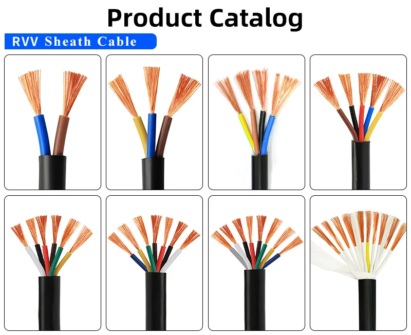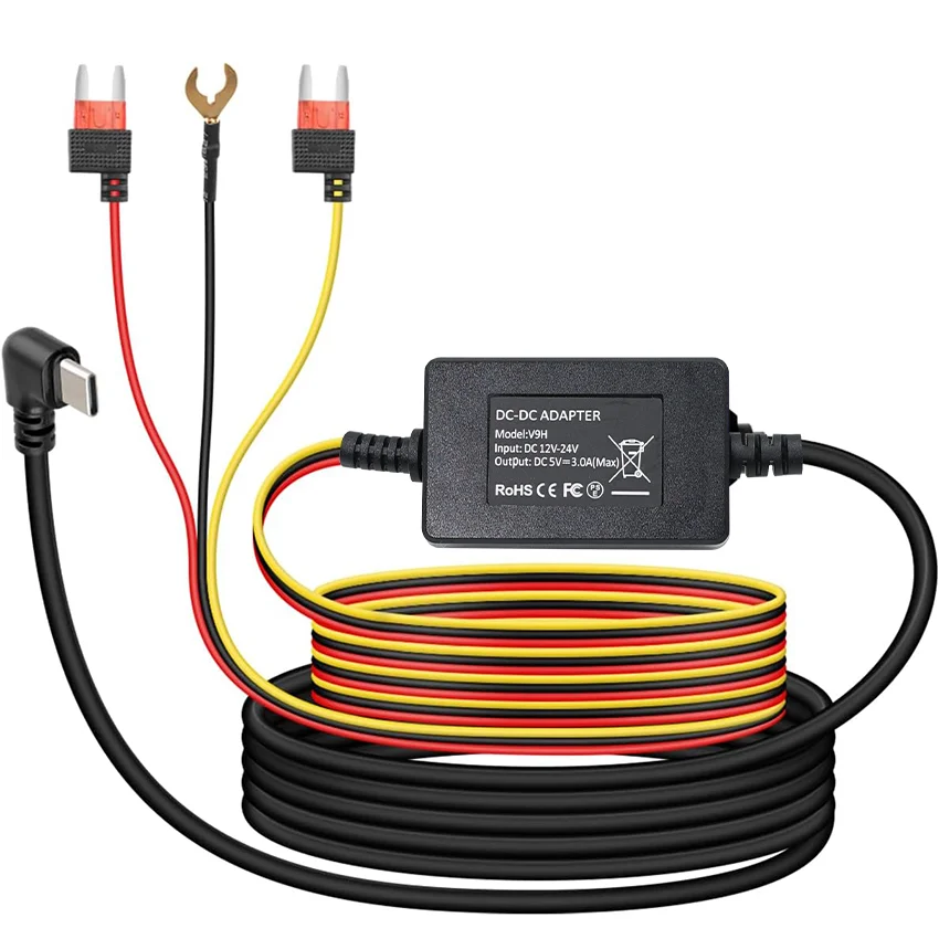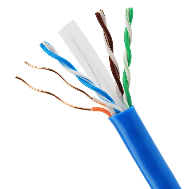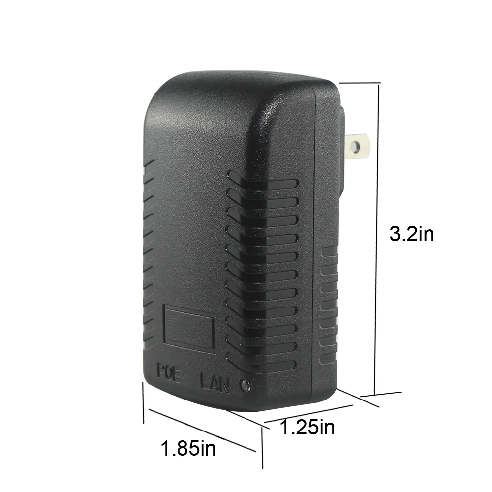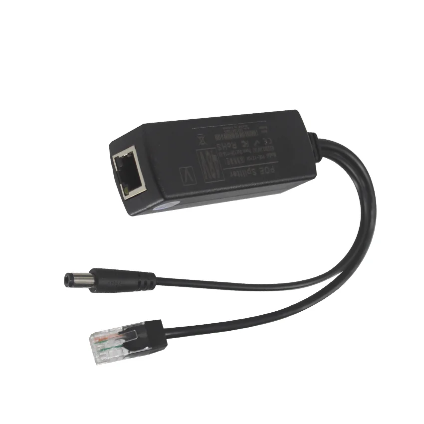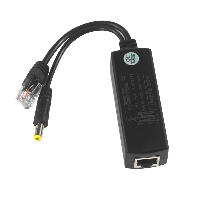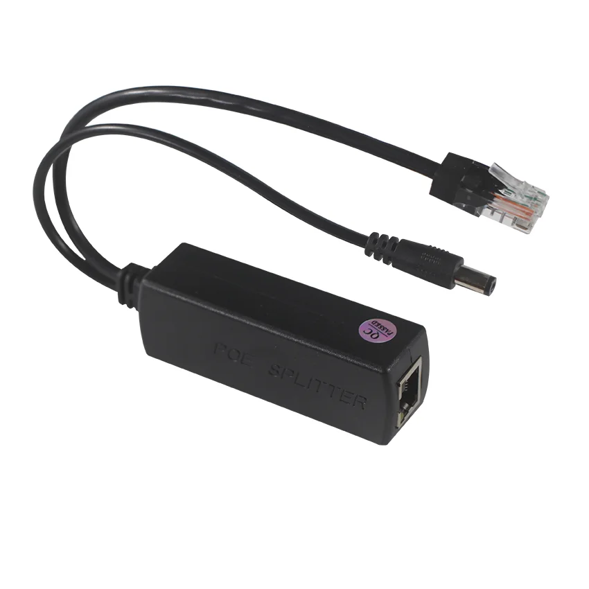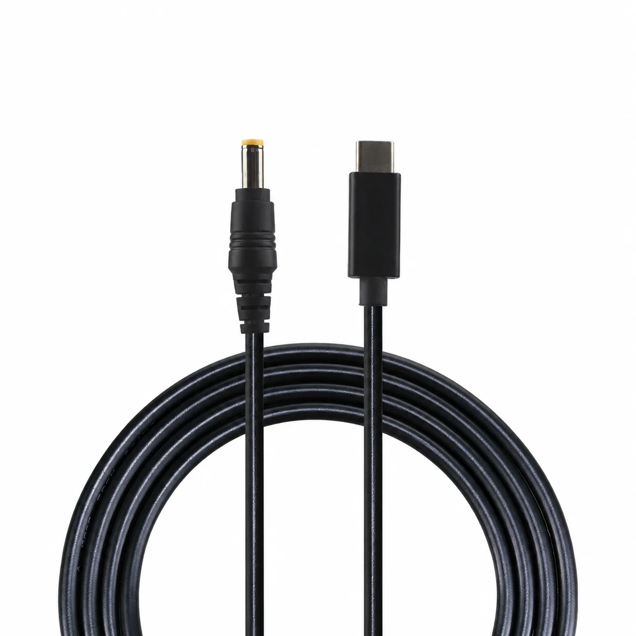
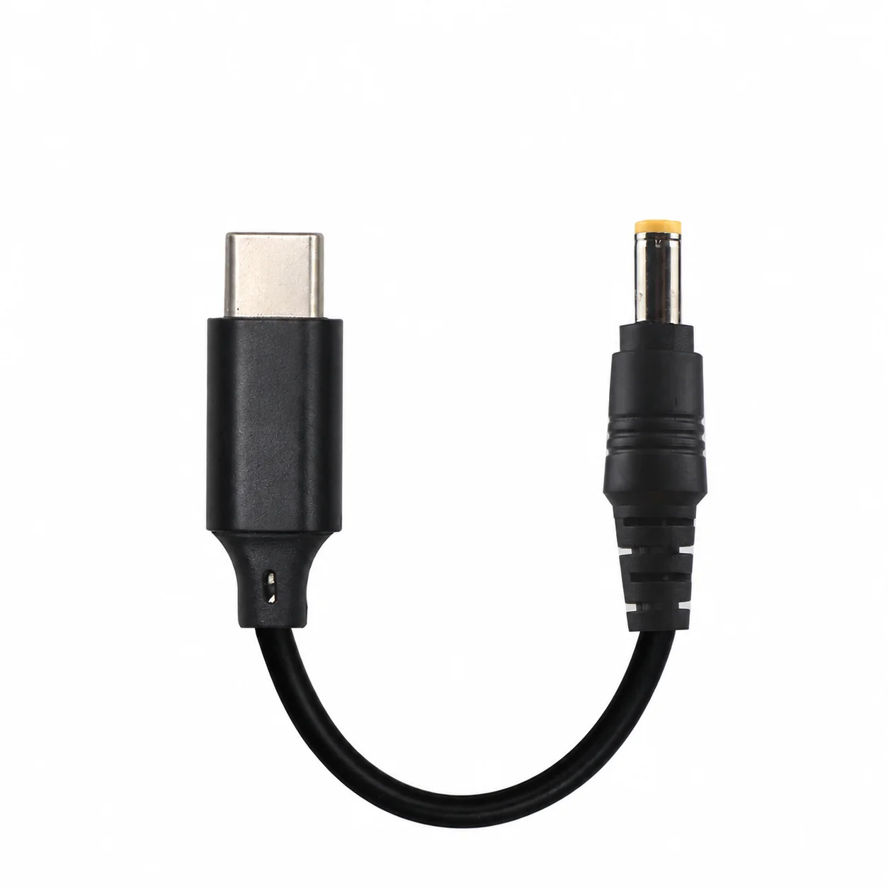
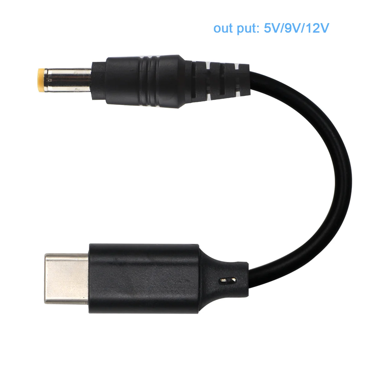
Series illustrations. Actual configuration is subject to the confirmed drawing.
USB-C to DC5521 PD Trigger Power Cord for Mini PC CCTV Camera | Copper PVC Selected Profile
-
Quotation & delivery: Include your required quantity, destination and timing in the enquiry. Confirm the selected build, lead time, shipping charges and any return terms in the agreed quotation before ordering.
-
Conductor materialCopper
-
connectorsUSB 2.0 ConnectorfunctionEco-Friendly, charging
-
materialPVCTypeUSB-C to DC PD Trigger Cable
-
usb typeType-C
-
conductorPure CopperjacketPVC
-
private moldYesshieldingNon-Shielded
-
useTablettypeUSB-C to DC PD Trigger Cable
-
cablepvc jacketcable wire2464 28awg,24awg,20awg
-
JacketPVCvoltage5v 9V 12V 15V 20V
-
cable colorblacklength1m,1.2m,1.5m,1.8m,2m,3m
-
connectornickel ,goldCertificationRoHS
This black USB-C-to-DC5521 power-cord request features a PD-trigger charging role for mini-PC, CCTV-camera or tablet equipment. Pure-copper conductors, PVC construction and a non-shielded build accompany actual length choices from half a meter to three meters.
Identify the receiving equipment input
Confirm the actual mini-PC, camera or tablet power connection and required 5.5 × 2.1 mm barrel interface. Agree both connector genders, polarity and pin assignment with the source and device so the supplied end arrangement is clear.
Choose the trigger-output configuration
Select the actual 5, 9, 12, 15 or 20 V profile with its complete current and power requirement. Match the PD source and trigger arrangement with the receiving-device input for that configuration.
Keep the charging function associated with the actual power path. The selected voltage/current and supplied construction should describe the same cord and equipment connection.
Agree the wire and connector finish
Choose 2464 wire construction in 28, 24 or 20 AWG and the required nickel or gold connector finish. Retain the black pure-copper/PVC non-shielded build with those selected physical and electrical details.
Define applicable USB/data requirements with the actual equipment where needed. Supporting function conditions should belong to the complete selected connection.
Set the exact installation reach
Actual lengths are 0.5, 1, 1.2, 1.5, 1.8, 2 and 3 m. Measure the source-to-device route and choose the supplied dimension alongside available connector space.
Complete the mini-PC/camera power-cord brief with exact reach, actual ends/polarity, wire, finish and trigger profile. These choices define the cord for its particular receiving device and power source.
Provide the product reference, selected configuration, quantity and destination. Confirm drawings, applicable ratings and acceptance requirements for the requested build. Lead time, shipping arrangements, charges and any return conditions should be reviewed in the agreed quotation before ordering.