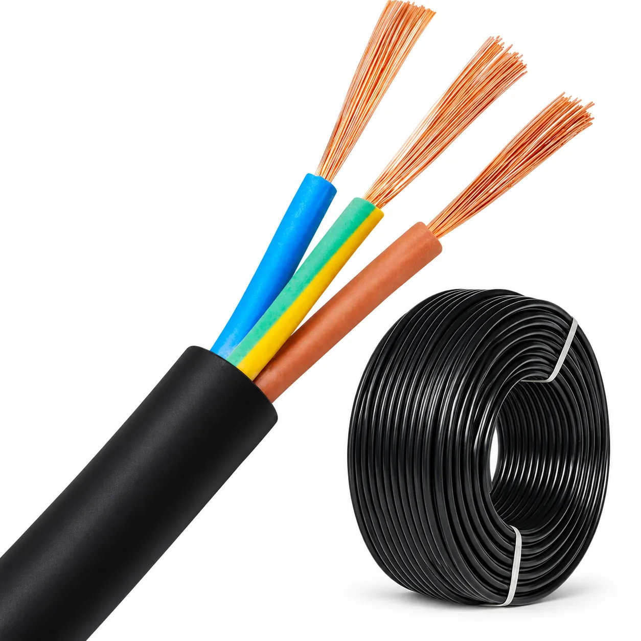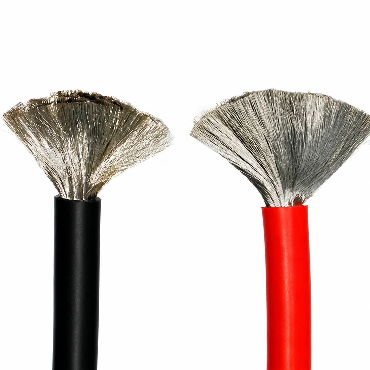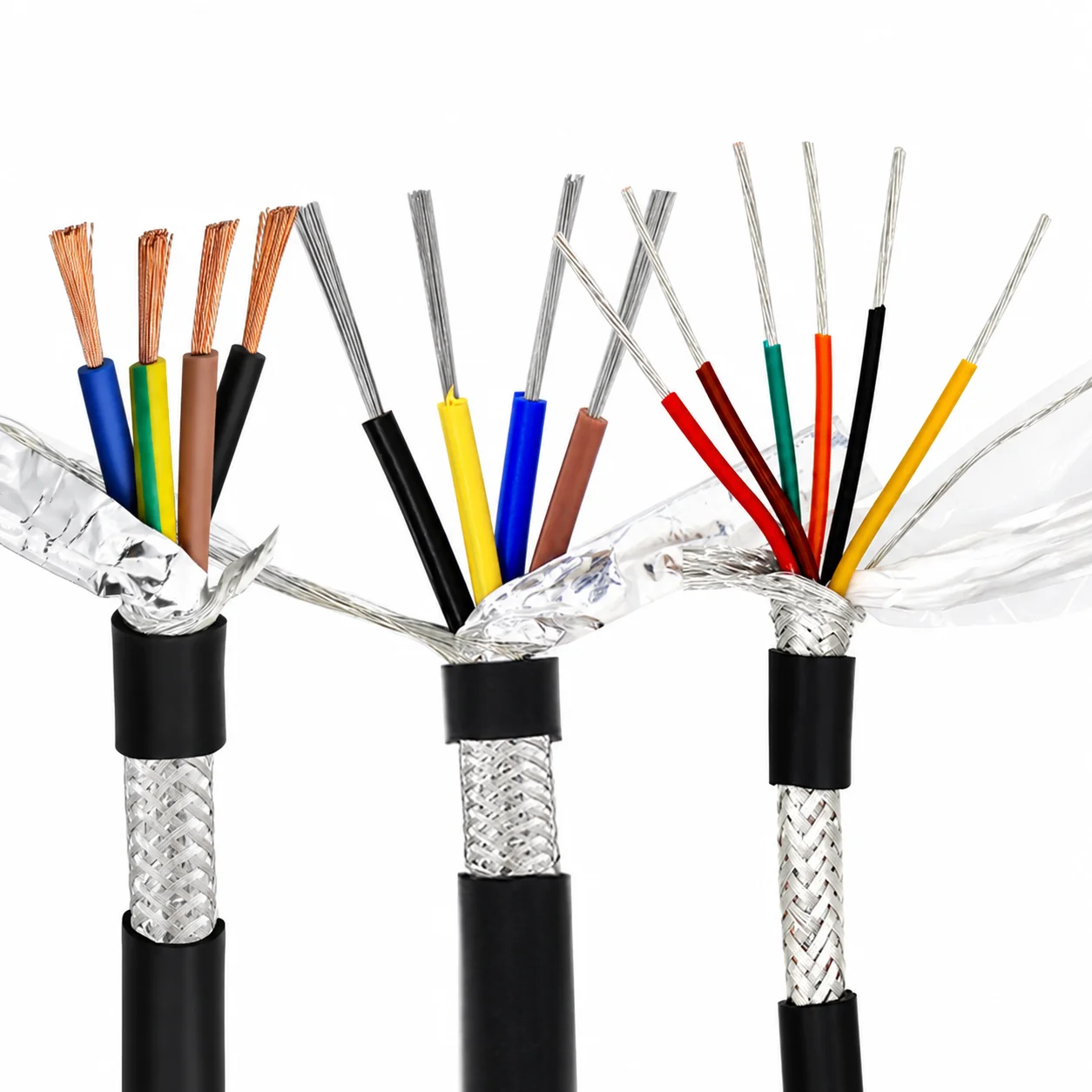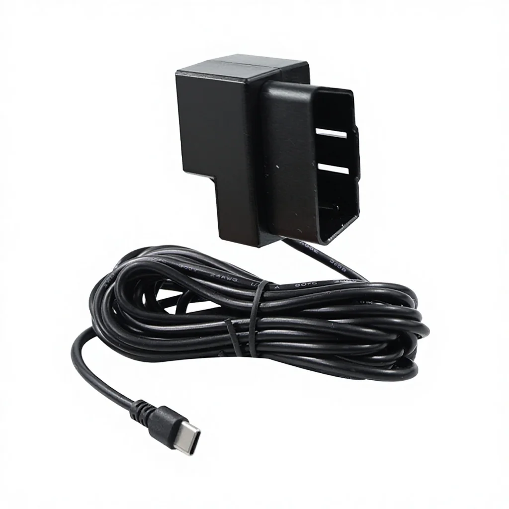
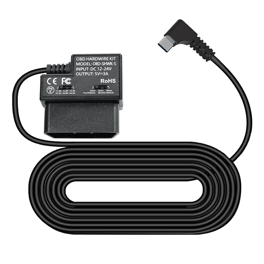
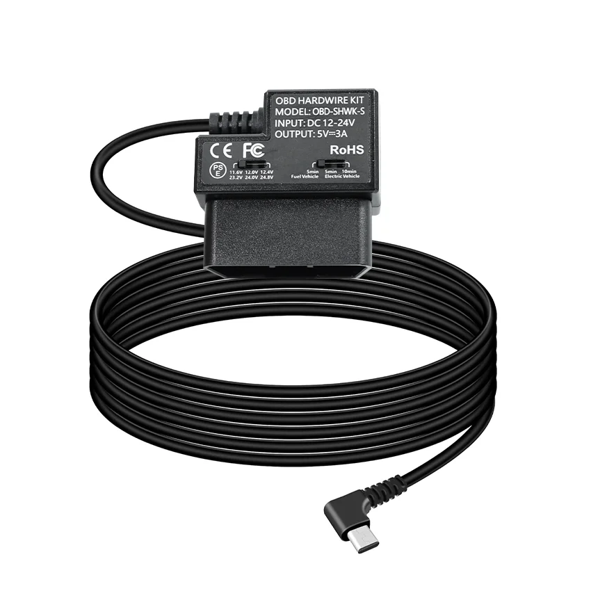
Series illustrations. Actual configuration is subject to the confirmed drawing.
OBD-II to USB-C Dash Cam Hardwire Power Kit | 12V-24V to 5V 3A Low-Voltage ACC Modes
-
Quotation & delivery: Include your required quantity, destination and timing in the enquiry. Confirm the selected build, lead time, shipping charges and any return terms in the agreed quotation before ordering.
-
End connectionUSB connectionInsulation materialPVC
-
Conductor materialCopper
-
Conductor MaterialCopper CoreConnector TypeUSB, OBD II Male + Type-C (USB-C) Male
-
Insulation MaterialPVCLength1m(3.28ft)
-
Rated Voltage12V
-
ApplicationMotorcycle, ElectronicIP LevelIP20
-
Jacket MaterialPVCSizeNO
-
Product TypeOBD Hardwire Kit / OBD Power CableInput VoltageDC 12V-24V (Car/Truck Battery)
-
Output Voltage/CurrentDC 5V 3AProtection FunctionLow Voltage Protection, Over-current Protection
-
Working ModeConstant Power / ACC (Ignition) Mode SwitchableCable Length3.5m (Standard, customizable available)
-
CertificationsCE, FCC, RoHSCompatibilityAll OBD II compliant vehicles,dash cam, GPS, car DVR, etc.
-
MaterialABS Plastic Housing, Pure Copper Core Cable
This OBD-II-to-USB-C power kit brings a dash-cam supply connection into a black copper-core PVC cable with ABS housing. The featured conversion is DC 12–24 V input to 5 V/3 A output, with low-voltage and overcurrent protection and switchable constant-power/ACC ignition modes.
Choose how the camera receives power
Agree the required constant-power or ACC ignition behavior with the vehicle and camera installation. Retain the low-voltage protection function and define the actual cutoff conditions for the selected supply arrangement.
Match the complete output voltage/current and receiving-device demand with that operating mode. Dash-cam, GPS and car-DVR requirements should be associated with the actual selected device rather than assumed from the USB-C connector alone.
Check the OBD and USB-C mating
The featured ends are OBD-II male and USB-C male. Confirm vehicle socket fit, pin assignment and the camera connection, identifying where the selected two-core/2P wiring applies within the complete assembly.
The input and wiring brief should describe the actual vehicle power path. Keep component-wire details distinct from the complete OBD interface when agreeing the supplied kit.
Resolve the installed cable reach
Agree whether the supplied assembly uses 1 m, 3.5 m or a custom length. Measure the route between the OBD location and receiving device, retaining the chosen reach with the black finish, copper core, PVC insulation/jacket and ABS housing.
Complete the protection and installation brief
Bring mating, pinout, input/output, selected power mode and cable reach together for the installation. Obtain applicable ingress and approval support where required, while retaining the actual low-voltage and overcurrent functions in the supplied kit specification.
Provide the product reference, selected configuration, quantity and destination. Confirm drawings, applicable ratings and acceptance requirements for the requested build. Lead time, shipping arrangements, charges and any return conditions should be reviewed in the agreed quotation before ordering.